Tugas 3. Rangkuman Gerbang Logika Aljabar Boolean
Gerbang Logika dan Aljabar Boolean
- Sekarang kita telah mengetahui konsep bilangan biner, dan kita akan mempelajari cara menggambarkan bagaimana sistem menggunakan menggunakan level logika biner dalam membuat keputusan.
- Aljabar Boolean adalah alat yang penting dalam menggambarkan, menganailisa, merancang, dan mengimplementasikan rangkaian digital.
Konstanta Boolean dan Variabel.
- Aljabar Boolean dibawah ini hanya mempunyai dua nilai : O dan 1.
- Logika 0 dapat dikatakan : false, off, low, no, saklar terbuka.
- Logika 1 dapat dikatakan: true, on, high, yes, saklar tertutup.
- Tiga operasi logika dasar: OR, AND, dan NOT.
Tabel Kebenaran
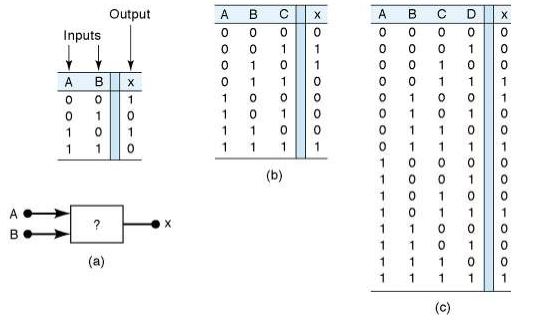
- Sebuah tabel kebenaran menggambarkan hubungan antara input dan ouput sebuah rangkaian logika.
- Jumlah The number of entries corresponds to the number of inputs. For example a 2 input table would have 2^2 = 4 entries. A 3 input table would have 2^3 = 8 entries.
Tabel Kebenaran
Contoh tabel kebenaran dengan masukan 2, 3 dan 4 buah
Operasi OR dengan gerbang OR
- The Boolean expression for the OR operation is X=A+B
- This is read as “x equals A or B.”
- X=1whenA=1orB= 1.
- Truth table and circuit symbol for a two input OR gate:

OR Operation With OR Gates
- The OR operation is similar to addition but when A = 1 and B = 1, the OR operation produces 1+ 1 = 1.
- In the Boolean expression
x=14+1+1=1
We could say in English that x is true (1) when A is true
(1) OR B is true (1) OR C is true (1).
OR Operation With OR Gates
- There are many examples of applications
- where an output function is desired when
- one of multiple inputs is activated.

AND Operations with AND gates
- The Boolean expression for the AND operation is
X=A°?B - This is read as “x equals A and B.”
- xX=1whenA=1andB=1.
- Truth table and circuit symbol for a two input AND gate are
shown. Notice the difference between OR and AND gates.

Operation With AND Gates
- The AND operation is similar to multiplication.
- In the Boolean expression
X=A'B'C
X =1 only whenA= 1, B=1, andC = 1.
NOT Operation
- The Boolean expression for the NOT
- operation is
X=A - This is read as:
- x equals NOT A, or
- x equals the inverse of A, or
- x equals the complement of A
NOT Operation
Truth table, symbol, and sample waveform
for the NOT circuit.

Describing Logic Circuits Algebraically
- The three basic Boolean operations (OR, AND, NOT) can describe any logic circuit.
- If an expression contains both AND and OR gates the AND operation will be performed first, unless there is a parenthesis in the expression.
Describing Logic Circuits Algebraically
e Examples of Boolean expressions for logic
circuits:

Describing Logic Circuits Algebraically
- The output of an inverter is equivalent to the
input with a bar over it. Input A through an
inverter equals A - e Examples using inverters.

Evaluating Logic Circuit Outputs
- Rules for evaluating a Boolean expression:
- Perform all inversions of single terms.
- Perform all operations within parenthesis.
- Perform AND operation before an OR operation
unless parenthesis indicate otherwise. - lf an expression has a bar over it, perform the
operations inside the expression and then invert
the result.
Evaluating Logic Circuit Outputs
Evaluate Boolean expressions by substituting
values and performing the indicated
operations:
A=0,B=1,C=l,and D=1
x = ABC(A +D)
=0-1-1-(0+1)
=1-1-1-(0+1)
=1-1-1-(1)
=1-1-1-0
=0
Evaluating Logic Circuit Outputs
- Output logic levels can be determined directly from a circuit diagram.
- The output of each gate is noted until a final output is found.
Implementing Circuits From $:
Boolean Expressions
- tis important to be able to draw a logic circuit from a
Boolean expression. - The expression
x=A-B-C
could be drawn as a three input AND gate. - Amore complex example such as
y =AC+BC+ABC - could be drawn as two 2-input AND gates and one 3-input
AND gate feeding into a 3-input OR gate. Two of the AND
gates have inverted inputs.
NOR Gates and NAND Gates
- Combine basic AND, OR, and NOT
operations. - The NOR gate is an inverted OR gate. An
inversion “bubble” is placed at the output - of the OR gate.
The Boolean expression Is, x-=A+B
NOR Gates and NAND Gates
- The NAND gate is an inverted AND gate.
An inversion “bubble” is placed at the
output of the AND gate. - The Boolean expression is
x = AB
NOR Gates and NAND Gates
- The output of NAND and NOR gates may be
found by simply determining the output of an
AND or OR gate and inverting it. - The truth tables for NOR and NAND gates
show the complement of truth tables for OR
and AND gates.
Universality of NAND and NOR Gates
- e NAND or NOR gates can be used to create
the three basic logic expressions (OR, AND, and INVERT) - This characteristic provides flexibility and is
very useful in logic circuit design.

Combinations of NANDs are used to create the three logic functions.

combinations of NORs are used to create the three logic functions.


Application

Application

Exercise

Exercise

Summary of Methods to Describe Logic Circuits
- The three basic logic functions are AND, OR, and NOT.
- Logic functions allow us to represent adecision process.
- lf it is raining OR it looks like rain | will take an
umbrella. - lf | get paid AND | go to the bank | will have
money to spend.


Comments
Post a Comment